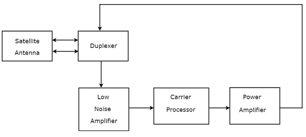
The basic block diagram of an vsat earth station transmitter is as shown in fig 2.
C band satellite transponder block diagram.
The function of each block is mentioned below.
The same is explained below with the use of the block diagram.
It is mainly used in satellite communication to transfer the received signals.
As shown in the figure satellite transponder receives signal of say 6175 mhz from the earth it converts the same to 3950 mhz by substracting it using lo of 2225 mhz.
The two way communication is established with the help of transponder a com satellite has multi transponder per satellite has in creased over the year a satellite with 2 transponder can support a signal t v channel or 240 telephone lines a satellite with 48 transponder can accommodate 4000t.
The number of transponders or channels indicates the capacity of the satellite.
Explain simplified block diagram of satellite transponder 1 single convention in c band 2 double conversion in ku band.
The communication is through a telecommunication link established between the control station on the ground and the satellite.
The block diagram of transponder is shown in below figure.
Duplexer is a two way microwave gate.
1 duplexer is a two way microwave gate.
It receives uplink signal from the satellite antenna and transmits downlink signal to the satellite antenna.
A block diagram of a transponder.
The block diagram of transponder we can easily understand the operation of transponder from the block diagram itself.
Each transponder is amplified by either a travelling wave tube am plifier twta or a solid state power amplifie r.
The ttc transponder on the spacecraft plays the role of radio frequency interface with the ground.
Usually in geo operate at the c band around 6 ghz.
Maurizio di paolo emilio.
Block diagram of a typical ttc transponder.
An input band limiting device an input band pass filter.
The function of each block is mentioned below.
A transponder is typically composed of.
This is for c band satellite band.
It receives uplink signal from the satellite.
Rain attenuation and sky noise is low at 4 ghz downlink frequency of c band.
8 m 10 m.
Satellite communication system block diagram.
A communications satellite s transponder is the series of interconnected units that form a communications channel between the receiving and the transmitting antennas.
Extended c band is most popular because of less propagation problem.
So it is possible to build a receiving system.
Signals traveling from earth to satellites must travel through the atmosphere.
Satellite transponder does this operation.
The block diagram of transponder is shown in below figure.
Extended c band communications satellite wi ll be examined briefly here.
An input low noise amplifier lna designed to.